Wheelchair Attachment for Infant Care
Alexander D. Streeter, M.S.
Division of Engineering, Mayo Clinic
Abstract
A quadriplegic woman recently had her first child. Working with her occupational therapist, the engineers at Mayo Clinic designed and built an attachment for her powered wheelchair that would position and support the baby facing her mother so that they could interact more often and intimately than would otherwise be possible. The device comprised a commercial infant car seat and welded aluminum frame with multiple degrees of freedom. The design was created in SolidWorks and its strength validated using finite element analysis before being built. The attachment has been used successfully since October 2007.
Keywords: wheelchair, infant care, parenting, adaptive equipment, finite element analysis
Background of the Problem
In mid-2007, the Division of Engineering (DOE) at Mayo Clinic in Rochester, Minnesota was contacted by Physical Medicine and Rehabilitation (PM&R) to design a custom attachment for a patient’s powered wheelchair. The patient, a 28 year old woman, was in her third trimester of pregnancy with her first child. Due to a cervical spinal injury years before, the woman had no use of her legs, limited strength and mobility in her arms, and got around in a powered wheelchair. The patient and her husband were working with an occupational therapist to plan the day-to-day care for their child. The OT wanted to find a way for the mother to have close, intimate contact and face-to-face interaction with her child. It is widely recognized that this contact and communication is essential for a parent and child to bond and grow together. The therapist feared that contact might be severely limited, because the mother didn’t have the strength to hold her child, and the infant would not be able to safely support itself for the first year or two. Being such a small market, commercial products to address this need are not available.
PM&R’s request was for an attachment for the mother’s wheelchair that would position and safely support the newborn facing her mother, and close enough that the mother could touch and tickle her child. The device would need several degrees of freedom so that the position of the baby could be adjusted. The device would need to be easy to remove so that it could be set aside when not in use. This device would be used until the child was about two years old, by which point she could support herself and ride on her mother’s lap. Naturally, the design would need to be lightweight to be easily used, yet incorporate a high factor-of-safety for strength.
Design of the Device
 Figure 1: CAD Assembly (Click for larger view)
 During design brainstorming sessions, the project team rallied around the following concept: a purchased infant car seat attached to an adjustable metal frame that could be quickly mounted to an adapter bolted to the mother’s wheelchair. Using an existing infant car seat seemed an obvious choice – they are ruggedly constructed yet lightweight, tested-to-death for safety, comfortable for the child, and have integrated restraints. The design of the frame – its adjustments, attachment, and construction – took longer. A view of the overall design, as it was implemented in SolidWorks 2007, is given in Figure 1.
 Figure 2: Degrees of Freedom(Click for larger view)
The adjustable frame consists of three main subassemblies. The first is the square bar at the base of the structure, which is the only portion of the device affixed to the mother’s wheelchair. It is bolted to the right side of the mother’s Permobil® powered wheelchair, just below the thigh. The bar is a length of extruded aluminum channel from Parker Scientific’s 40-mm Industrial Profile System® (IPS). The aluminum channel has a T-slot on each face, which allows for easy and adjustable attachment of other IPS components. The second subassembly is a frame consisting of a parallel linkage and tubular horizontal crossbar, also made of aluminum. The bottom of the parallel linkage is mounted to another IPS component – a bracket that wraps around and slides along the extruded channel. This bracket engages the T-slots of the IPS extrusion on three sides and has low-friction plastic bearing surfaces for smooth sliding. Finally, there is the hardware that attaches to the purchased infant seat and clamps around the tubular crossbar. The hardware sandwiches the thin injection-molded plastic of the seat between more durable metal, and provides a solid attachment.
 Figure 3: Locking Hinge(Click for larger view)
 The frame has three degrees of freedom, or ways that it can be adjusted. These degrees of freedom are indicated by the block arrows in Figure 2. The first is the front-to-back location of the sliding bracket along the IPS extrusion. The bracket can travel along the entire length of the extrusion, about 14”, or can slide all the way off the front end, allowing the frame and seat to be set aside when not in use. The position of the bracket is locked in place by tightening a handle at the base of the parallel linkage. The second adjustment is the “elevation angle” of the parallel linkage, which ranges from nearly horizontal to nearly vertical in 10º increments. The elevation angle is maintained by a purchased locking hinge assembly, shown in Figure 3, which makes up one of the upper pivot joints of the parallel linkage. Pushing in a button at the hub releases a series of pins, which allows the angle of the hinge to be adjusted. Releasing the button lets the pins lock into the next 10º location. Finally, there is the “pitch angle” of the infant seat about the horizontal crossbar, which has a range of +/- 22.5º from nominal. The pitch angle adjustment is made by loosening a handle underneath the infant seat, which loosens the clamp around the horizontal crossbar.
 Figure 4: Pitch Stop Cutaway (Click for larger view)
 For safety, the frame has several hard stops that limit the range of motion. At the rear end of the IPS extrusion is a permanent screw that prevents the sliding bracket from sliding all the way off the back end. At the front there is a quick pin that is removed when taking the adjustable frame on and off, but otherwise prevents the sliding bracket from sliding off the front end. The lower limit of the parallel linkage’s elevation angle – with the linkage nearly horizontal – is a limit built into the locking hinge itself. The upper limit – nearly vertical – is the result of interference between the members of the linkage. The locking hinge’s button faces inboard, lest it be activated accidentally by knocking against a wall, and must be pushed in continuously to change the elevation angle. Otherwise, the hinge will lock into the next 10º increment.
Because the pitch angle is maintained solely by the friction of the tube clamp, it too has a hard stop built in. The tube clamp has a pin that engages a slot cut circumferentially in the horizontal crossbar. The slot extends 45º around the crossbar, allowing the infant seat to tilt only +/- 22.5º from its nominal position. Even at its most downward position, there is no possibility for the baby to spill out of the seat. The pitch stop mechanism is shown in a cutaway view in Figure 4. The pin-and-slot assembly also prevents the tube clamp (and, by extension, the infant seat) from sliding off the end of the horizontal crossbar when the clamp is loosened.
Mechanical Simulation of the Device
During the design process, finite element analysis (FEA) in ANSYS Workbench v11.0 was used extensively to check the mechanical strength of the design and ensure there was an adequate factor-of-safety against breaking. FEA is a way to simulate the response of a mechanical system to the loads and constraints that it will encounter in real life. The results of these simulations inform iterative changes and refinements in the computer design before it is finalized. Each of the three subassemblies – the IPS extrusion bolted to the mother’s wheelchair, the adjustable frame, and the hardware that attaches to the infant seat – were simulated in different loading scenarios and use cases.
 Figure 5: Applied Loads (Click for larger view)
 As an illustration, we present one analysis done on the adjustable frame subassembly. The end of the horizontal crossbar, where the tube clamp contacts, has several loads applied to it. The weight of the infant (a typical two year-old weighs 28 lbs (1)), the infant seat, and the hardware attached to it are lumped into a conservative 50 lbs. That weight creates a 50-lb downward force on the crossbar, as well as a torque load of 300 in-lb. The tube clamp, because it is clamped tightly around the crossbar, also creates a 300-psi pressure load on the contact patch. Gravity acts on the frame, too, although this effect is small. These loads are transferred through the frame and ultimately supported by the base of the parallel linkage, which is modeled as a pair of pin joints. Refer to Figure 5. The frame is made almost entirely of 6061-T6 aluminum, while the locking hinge is heat-treated AISI 4140 steel.
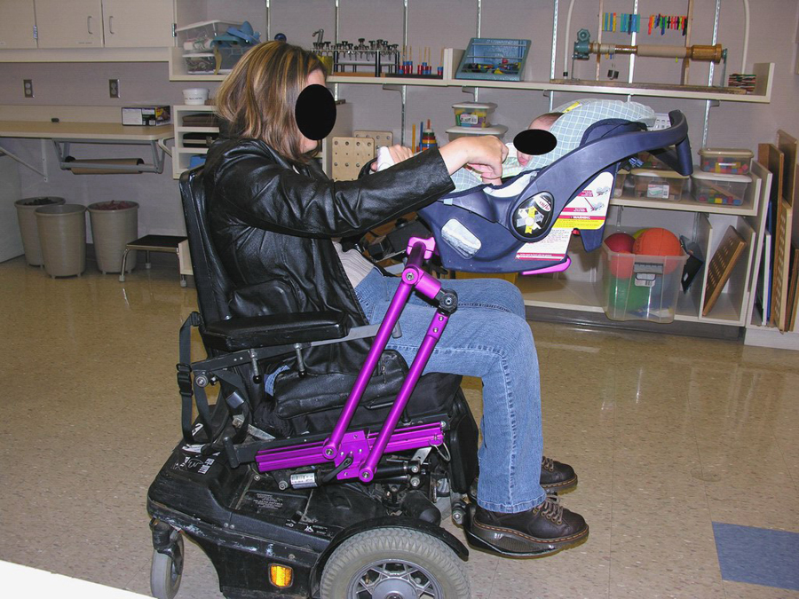 Figure 6: In Use Right (Click for larger view)
 The ANSYS finite element method solves for the deformation in the structure in response to the applied loads. However, engineers are more interested in stress results, as they are a more direct indicator of design strength. Going one step further, a more illustrative way to discuss the results is through the factor-of-safety, or the ratio of how large the stress at a particular point is in comparison to the material’s yield stress. A higher ratio is better. The point in the structure that has the lowest safety factor is like the weakest link in a chain – it is the most likely point of failure. In this particular simulation, the minimum safety factor occurs at the upper end of the lower arm of the parallel linkage, where the locking hinge inserts. The safety factor there is 3.8, which means it would take a load approximately 3.8 times larger than the applied load (that is, nearly 200 lbs) to cause the frame to yield. In some applications, a safety factor of 3.8 would indicate that the design could safely be slimmed down; in this case it is appropriate because the structure supports someone’s child (2).
With the design in SolidWorks complete and its strength validated by simulations in ANSYS, a set of measured drawings was drafted and the parts manufactured in-house. Before the final assembly, the aluminum parts were sent out for a durable anodized finish. The anodized color, bright purple, was the patient’s choice.
Outcome
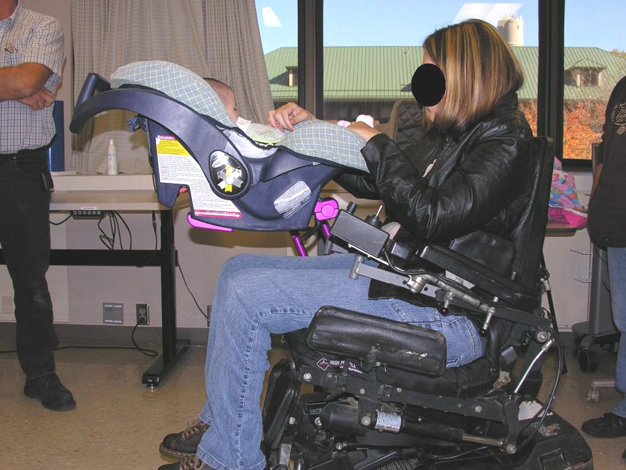 Figure 7: In Use Left(Click for larger view)
Figures 6 and 7 show the device installed on the mother’s wheelchair and in use with her baby. Since its delivery in October 2007 it has received daily use. It is easy for the father, or some other caregiver, to slide the 14-lb attachment on and off the wheelchair and place the baby in. The device is compact enough that it doesn’t hinder movement around the house, nor make the wheelchair unstable or tipsy. The mother has been very happy to be able to have such close interaction with her daughter. The mother is able to feed her child, read stories to her, play games with her, and physically console her when she becomes fussy. The mother is able to more fully participate in her parenting role, which was the overall goal of the project. The design was flexible enough that, when the mother received a newer model wheelchair in Spring 2008, the device could be installed with just one new part and no further modifications.
Periodic checks by the Division of Engineering have revealed no wear or maintenance issues, although preventative checks will continue through the life of the device. The parents should be able to use the device until the baby is about two years old, at which point she may be too heavy to use it, but strong enough to support herself on her mother’s lap.
References
- U.S. Centers for Disease Control and Prevention, “Growth Charts: Birth to 36 Months.” National Center for Health Statistics, May 2000, updated April 2001.
- Hamrock, B. J., Jacobson, B., and Schmid, S. R., Fundamentals of Machine Elements, McGraw-Hill, Boston, 1999, chapter 1.
- Vensand, K., et al., Adaptive Baby Care Equipment: Guidelines, Prototypes & Resources, Through the Looking Glass, Berkeley, 2000.
Author Contact Information
Alex Streeter, Mayo Clinic, 200 1st St. SW, Rochester, MN 55905. Office Phone 507-538-1595. Email streeter.alexander@mayo.edu